Photoluminescence spectroscopy
Photoluminescence (PL) spectroscopy is a group of optical methods for measuring optical emission spectra from nanoscale objects. PL spectra can provide information about optical emission, quantum states, intrinsic strain, and other characteristics of materials and nanostructures.
Photoluminescence spectroscopy
In a classical PL setup, the sample is directly excited by a laser with energy above the band gap. The emitted photons are collected by the detection system and sent to a monochromator equipped with a photodetector. A typical PL setup is shown below:

The sample is placed in a cryostat, with the possibility to change the temperature and pressure. The emitted light is collected by a spherical mirror system and focused on the entrance of an optical fiber, which leads the emitted photons to a monochromator equipped with a diffraction grating, and coupled to a liquid nitrogen cooled InGaAs or Si photodiode array detector. The reflected laser light is filtered off by a long-pass filter. Polarizers for excitation or collection can be added if needed.
Micro-Photoluminescence technique
To study spectra of nanoscale objects, the micro-photoluminescence (μPL) technique is widely used. The main difference between the μPL and the classical PL setup consists in the presence of an optical objective that is focusing the laser beam in a spot of a few microns in diameter.
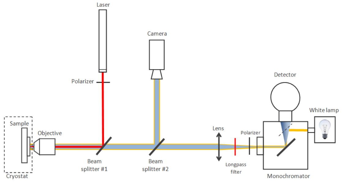
The configuration of the μPL setup used in this work is schematically illustrated in figure above. The laser beam (typically He-Ne laser 632 nm) is reflected by a dichroic beam splitter (#1), and focused by an optical objective (20x/0.4) on the sample, which can be placed into a continuous flow liquid He cryostat when necessary. The diameter of the laser spot is in the 2 – 5 µm range. To be able to see the surface of the sample on the monitor, a white lamp coupled with monochromator is used. The use of a monochromator allow us to choose a required wavelength (typically near infrared), so that the camera may detect the reflected light in the range far away from laser wavelength. The emitted light together with the reflected light of the white lamp are passing back through the objective, turning into a parallel beam, and passing through the first beam splitter, reflecting from the second beam splitter toward the infrared camera. So, having the information about the surface and the laser beam position on it, we are able to focus the laser beam at a certain point. After the focusing, the mirror inside the monochromator (dashed line) is switched to the position when the emitted light passes to the detector and the white lamp is turned off. The beam splitter #2 is removed in order to avoid a loss of signal. In this position, the PL emission can be focused at the entrance of the monochromator, inside of which, the diffraction grating splits the beam into a spectrum and reflects it to the liquid nitrogen cooled InGaAs photodiode array detector.
In order to conduct the experiments with various excitation wavelengths, the setup can be modified by the replacement of the laser with a second monochromator coupled with a white lamp. In this configuration it is possible to excite the sample using a chosen wavelength. Here and elsewhere a polarizer for visible range is used to polarize the laser beam, which, however, is not totally non-polarized, and thus angular function of laser intensity is used to correct all polarization dependent results. To analyze polarization of the emitted luminescence a polarizer for infrared range is used.
Both PL and μPL techniques were used extensively to study the optical emission, strain, polarization, and piezoelectric properties of InAs/InP nanowire heterostructures — see the Nanowire optics project for more details.
References
- “Optical properties of InAs/InP nanowire heterostructures” by R. Anufriev (2013)
- Anufriev et al. Applied Physics Letters 101, 072101 (2012)
- Anufriev et al. Journal of Applied Physics 113, 193101 (2013)
- Anufriev et al. Physica Status Solidi RRL 7, 878 (2013)
- Anufriev et al. Applied Physics Letters 104, 183101 (2014)